An operational amplifier ("op-amp") is a DC-coupled high-gain voltage amplifier. They are called "operational'' amplifiers, because they can be used to perform arithmetic operations (addition, subtraction, multiplication) with signals. In fact, op amps can also be used to integrate (calculate the areas under) and differentiate (calculate the slopes of) signals.
Ideally the op-amp amplifies only the difference in voltage between the two, which is called the differential input voltage.
$ \quad V_{out}=G(V_{+}-V_{-})$
$G$ is the open-loop gain of the amplifier ("open-loop": absence of a feedback loop from the output to the input). $G$ is typically very large 100,000 or more for integrated circuit op-amps.
The magnitude of $G$ is not well controlled by the manufacturing process, and so it is impractical to use an open loop amplifier as a stand-alone differential amplifier.
With very large $G$, a quite small difference between V+ and V− drives the amplifier output nearly to the supply voltage. Situations in which the output voltage is equal to or greater than the supply voltage are referred to as saturation of the amplifier.
Ideal Op-amp has

The output voltage of the op amp is linearly proportional to the voltage difference between the input terminals ${v_{in}=V_{+}-V_{-}}$ by a factor of the gain $G$. However, the output voltage is limited to the range $-V_S \leq v_{in} \leq V_S$, where $V_S$ is the supply voltage specified by the designer of the op amp. The range $-V_S \leq v_{in} \leq V_S$ is often called the linear region of the amplifier, and when the output swings to $V_S$ or $-V_S$, the op amp is said to be saturated.
When an op-amp operates in linear (i.e., not saturated) mode, the difference in voltage between the non-inverting (+) pin and the inverting (−) pin is negligibly small.
Negative saturation region: $V_{out}=-V_S $
Linear active region: $V_{out}=G(V_{+}-V_{-}); \quad -V_S<A<V_S $
Positive saturation region: $V_{out}=V_S $
http://www.electronics-tutorials.ws/opamp/op-amp-comparator.html
https://en.wikibooks.org/wiki/Electronics/Electronics_Formulas/Op_Amp_Configurations
Ideally the op-amp amplifies only the difference in voltage between the two, which is called the differential input voltage.

$ \quad V_{out}=G(V_{+}-V_{-})$
$G$ is the open-loop gain of the amplifier ("open-loop": absence of a feedback loop from the output to the input). $G$ is typically very large 100,000 or more for integrated circuit op-amps.
The magnitude of $G$ is not well controlled by the manufacturing process, and so it is impractical to use an open loop amplifier as a stand-alone differential amplifier.
With very large $G$, a quite small difference between V+ and V− drives the amplifier output nearly to the supply voltage. Situations in which the output voltage is equal to or greater than the supply voltage are referred to as saturation of the amplifier.
Ideal Op-amp has
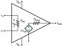
- Infinite open-loop gain; $G=\frac{V_{out}}{V_{+}-V_{-}}$
- Infinite input impedance Rin, and so zero input current
- Zero output impedance Rout
- Infinite bandwidth with zero phase shift and infinite slew rate
- Infinite Common-mode rejection ratio (CMRR)
- Infinite Power supply rejection ratio
The output voltage of the op amp is linearly proportional to the voltage difference between the input terminals ${v_{in}=V_{+}-V_{-}}$ by a factor of the gain $G$. However, the output voltage is limited to the range $-V_S \leq v_{in} \leq V_S$, where $V_S$ is the supply voltage specified by the designer of the op amp. The range $-V_S \leq v_{in} \leq V_S$ is often called the linear region of the amplifier, and when the output swings to $V_S$ or $-V_S$, the op amp is said to be saturated.
When an op-amp operates in linear (i.e., not saturated) mode, the difference in voltage between the non-inverting (+) pin and the inverting (−) pin is negligibly small.
Negative saturation region: $V_{out}=-V_S $
Linear active region: $V_{out}=G(V_{+}-V_{-}); \quad -V_S<A<V_S $
Positive saturation region: $V_{out}=V_S $
Solving circuits involving OPAMPs:
While solving OPAMP circuits, follow two rules:- No Current Flows into the Input Terminals
- The Differential Input Voltage is Zero as $V_+ = V_- $
Using the above two rules, apply nodal analysis or mesh analysis in the circuit to solve for current or voltage. Examples: Inverting amplifier, Non-inverting amplifier, Inverting integrator
Different Op-amp circuits:
- Comparator
- Inverting amplifier
- Non-inverting amplifier
- Differential amplifier
- Voltage follower
- Summing amplifier
- Inverting integrator
- Inverting differentiator
- Schmitt trigger
- Inductance gyrator
- Negative impedance converter (NIC)
- Instrumentation amplifier
Resources:
http://webpages.ursinus.edu/lriley/ref/circuits/node5.htmlhttp://www.electronics-tutorials.ws/opamp/op-amp-comparator.html
https://en.wikibooks.org/wiki/Electronics/Electronics_Formulas/Op_Amp_Configurations