A capacitor is a passive electrical component used to store energy electrostatically in an electric field. A resistor dissipates energy, whereas a capacitor stores energy. Typical capacitance values range from about 1 pF (10−12 F) to about 1 mF (10−3 F). Capacitors are widely used in electronic circuits for blocking direct current while allowing alternating current to pass.

An ideal capacitor is wholly characterized by a constant capacitance C, defined as the ratio of charge ±Q on each conductor to the voltage V between them:
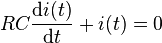
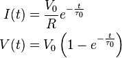
 If the capacitor is initially uncharged while the switch is open, and the switch is closed at t0, it follows from Kirchhoff's voltage law that:
The −j phase indicates that the AC voltage V = ZI lags the AC current by 90°.
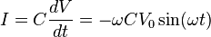
A capacitor connected to a sinusoidal voltage source will cause a displacement current to flow through it. In the case that the voltage source is V0cos(ωt), the displacement current can be expressed as:
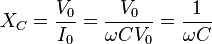
XC approaches zero as ω approaches infinity. If XC approaches 0, the capacitor resembles a short wire that strongly passes current at high frequencies. XC approaches infinity as ω approaches zero. If XC approaches infinity, the capacitor resembles an open circuit that poorly passes low frequencies.
The current of the capacitor may be expressed in the form of cosines to better compare with the voltage of the source:


An ideal capacitor is wholly characterized by a constant capacitance C, defined as the ratio of charge ±Q on each conductor to the voltage V between them:


DC circuits

AC circuits
Impedance, the vector sum of reactance and resistance, describes the phase difference and the ratio of amplitudes between sinusoidally varying voltage and sinusoidally varying current at a given
frequency.
The reactance and impedance of a capacitor are respectively
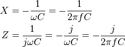
The −j phase indicates that the AC voltage V = ZI lags the AC current by 90°.
A capacitor connected to a sinusoidal voltage source will cause a displacement current to flow through it. In the case that the voltage source is V0cos(ωt), the displacement current can be expressed as:
XC approaches zero as ω approaches infinity. If XC approaches 0, the capacitor resembles a short wire that strongly passes current at high frequencies. XC approaches infinity as ω approaches zero. If XC approaches infinity, the capacitor resembles an open circuit that poorly passes low frequencies.
The current of the capacitor may be expressed in the form of cosines to better compare with the voltage of the source:

Parallel and series connection